I thought I’d write up my experience of retrofitting CAT6 ethernet cable in a Taylor Wimpey Flatford built around 2015.
It’s a very long post, but I wanted to share as many pictures/details of what I did to help anybody hoping to do the same. I had the cables in within 5-6 hours of work. I think it’d be quicker knowing what I know now!
Before I started my project, I did a load of Googling and found nothing which really inspired much confidence in what I was about to do. Hopefully someone will stumble across this in the future and it’ll help them know what to expect.
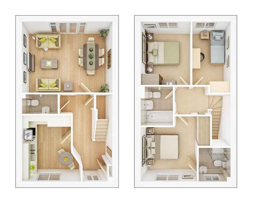
Despite my house being fairly modern, it was not fitted with network cables which meant I had to rely on Wi-Fi. While that seems to work well for some, I had endless problems with bandwidth, latency and general connectivity using the BT-provided ‘Smart Hub’ and an ASUS mesh-based setup.
I don’t know why my luck was so bad, perhaps it was my choice of equipment, the way my house is constructed, something to do with other Wi-Fi networks around me (I spent forever changing channels, trying 2.4GHz/5GHz). My internal walls use metal studs. I don’t know if that has anything to do with it, but if someone does know, please leave a comment!
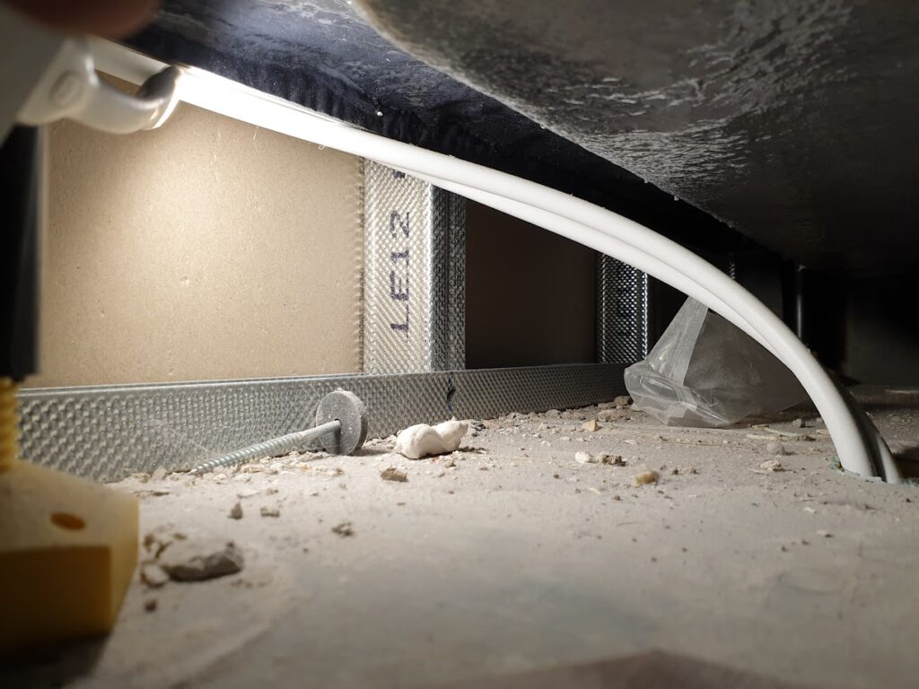
Anyway, I didn’t want to keep trying different Wi-Fi based systems in the hope that one would remain stable, and powerline adapters aren’t fast/reliable enough to get the most out of my gigabit fibre-to-the-premises (FTTP) connection, so I decided it was time to get some network cables in.
Plan A
Because my office and the cupboard under the stairs, where the BT OpenReach modem is, are super close, my first plan was to run a cable along the wall, down through the floor and into the cupboard
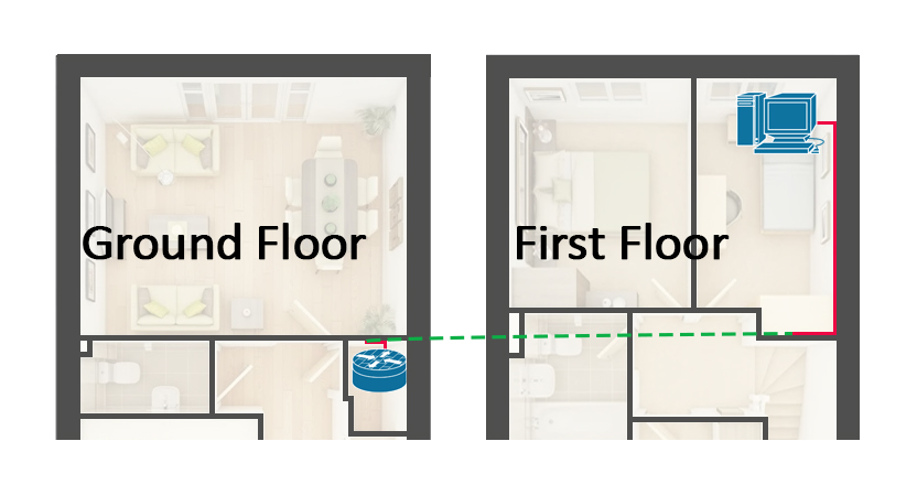
I pulled back the carpet, tapped around on the floor boards and it sounded solid from the red line over to the wall.
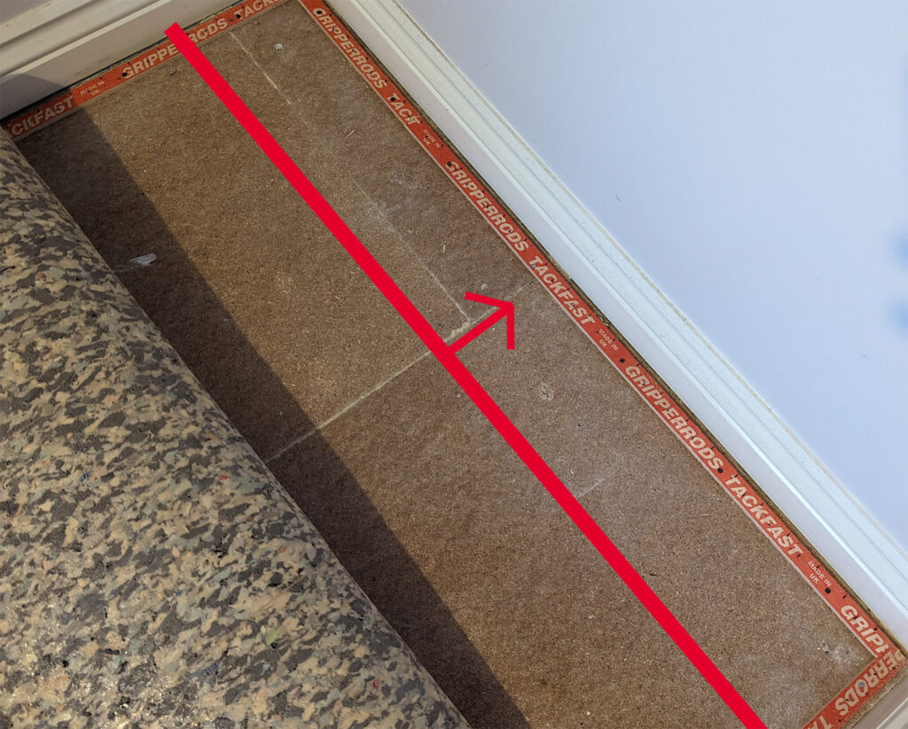
I wasn’t willing to start drilling through what is likely structural wood in the hope that I’d find a way through. I couldn’t easily lift the floorboards because they go underneath the plasterboard walls. Mission failed.
Plan B
After a bit more research, I found Running RJ45 Network Cables inside walls …and fixing Wi-Fi problems! by Gosforth Handyman who inspired me to look into running cables up to the loft via the boxing which wraps around the vent/soil stack inside the bathrooms. From there, I can run the cables down to each room I need connectivity in. The stack’s boxing provides a perfectly vertical route from the ground floor up to the loft.
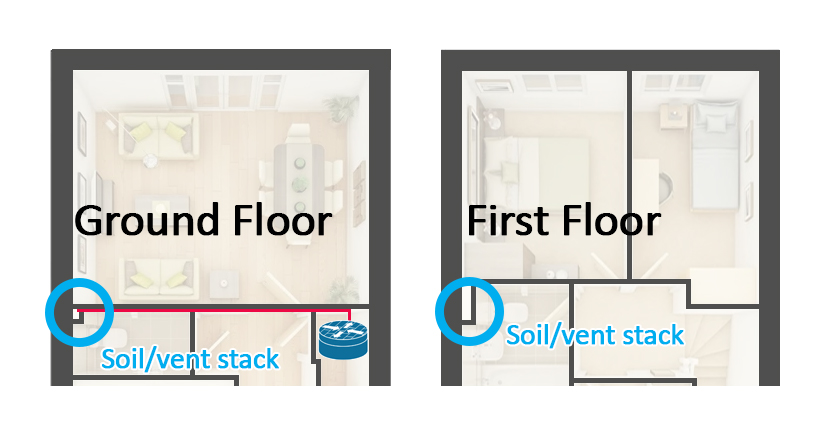
Fortunately, my router is directly across the house from the vent stack and I knew that my joists ran in the same direction. It was time to start drilling to see if I had a clear path across. Again, I was not willing to make holes in structural timber.
A bit about cutting holes
I went to Screwfix and picked up an Erbauer Hex Shank Holesaw Arbor 11mm and Erbauer Multi-material Holesaw 92mm. I went for 92mm as I figured I could get enough of my arm through the hole(s) in the plasterboard to be able to push/pull cables around.
Unfortunately, I didn’t take a picture of the contraption I made, but I:
* took the long side of a metal coat hanger, snipped it at either end so I was left with an | shaped piece of metal.
* bent it into an L shape, with the short edge being 20mm longer than the diameter of the 92mm hole saw
* drilled a small hole in the middle of where I’d use the hole saw
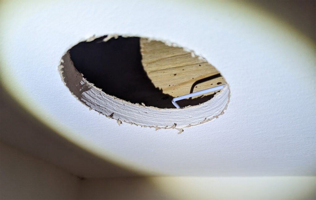
* poked the short edge of the L shaped coat hanger through the hole and curved it into the space above the ceiling’s plasterboard
* rotated the coat hanger a full 360 degrees, at varying depths into the ceiling void

I then had confidence that I wouldn’t drill into a joist, pipe or cable. I held a paint roller tray underneath the drill and made the first hole.
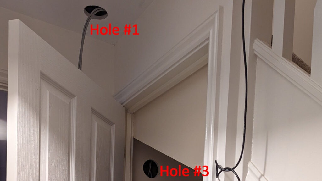
Hole #1
I picked this spot as it was close to the cupboard, where I need the cable run to start, and should give me a clear view, between the joists, of what’s between the cupboard and the vent stack. This was the part of the cable run which would most likely cause me problems, so I wanted to know early
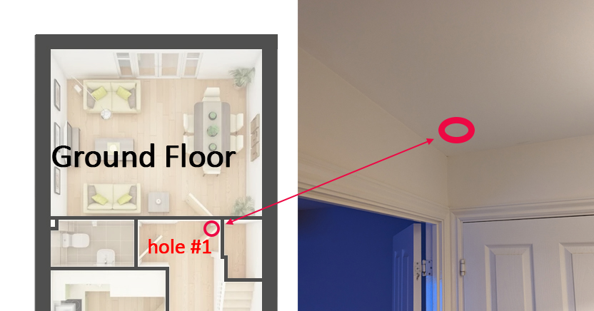
With a combination of tracing popped screw heads in the ceiling plasterboard, along the joists, and my stud finder, I located two joists and picked a spot in between.
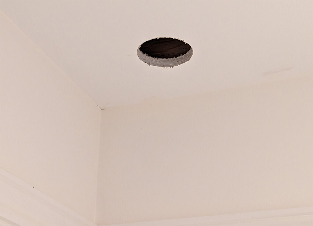
I poked my phone into the hole and looked towards the vent stack and to my surprise, I had a clear run across!
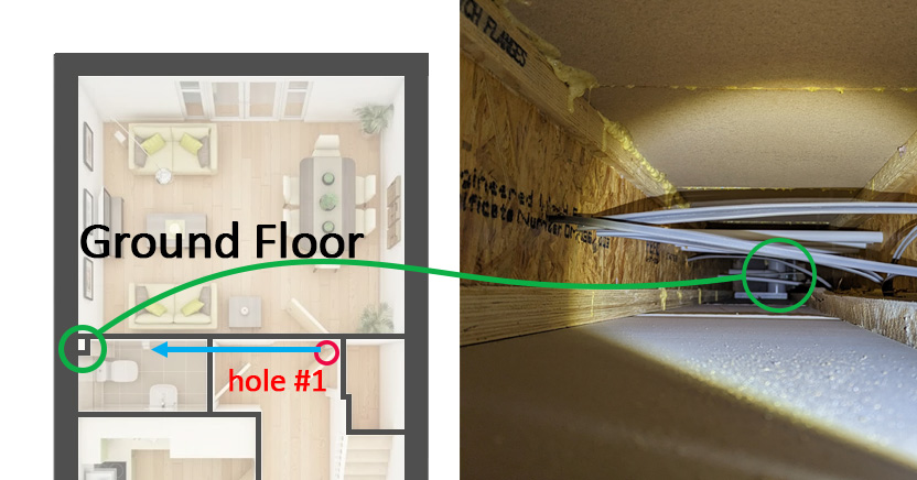
Turning the camera 180 degrees towards the cupboard, I found a small gap between the top of the plasterboard and a piece of wood.
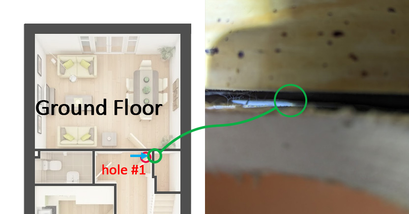
I cut the long end of my coat hanger contraption at a 45 degree angle to make it sharp enough to push through plasterboard, with some twisting/force, and into the space above the cupboard ceiling.
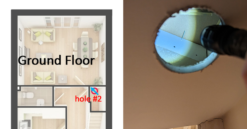
Hole #2
Using the same technique as describe for hole #1, (exploratory hole, poke around with coat hanger, hole saw), I cut hole #2 in the cupboard ceiling and found the other coat hanger poking through.
Hole #3
Repeating the same process, I cut hole #3 in the wall between the lounge and cupboard so I could fish the cables down the wall and into wall sockets.
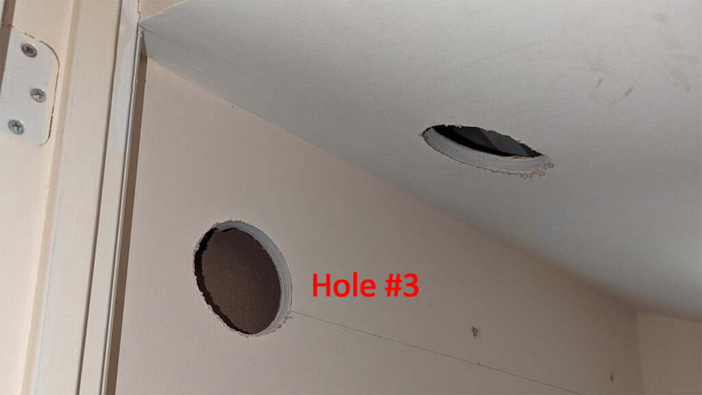
I cut a hole where I wanted the RJ45 sockets to be in the cupboard, below hole #3
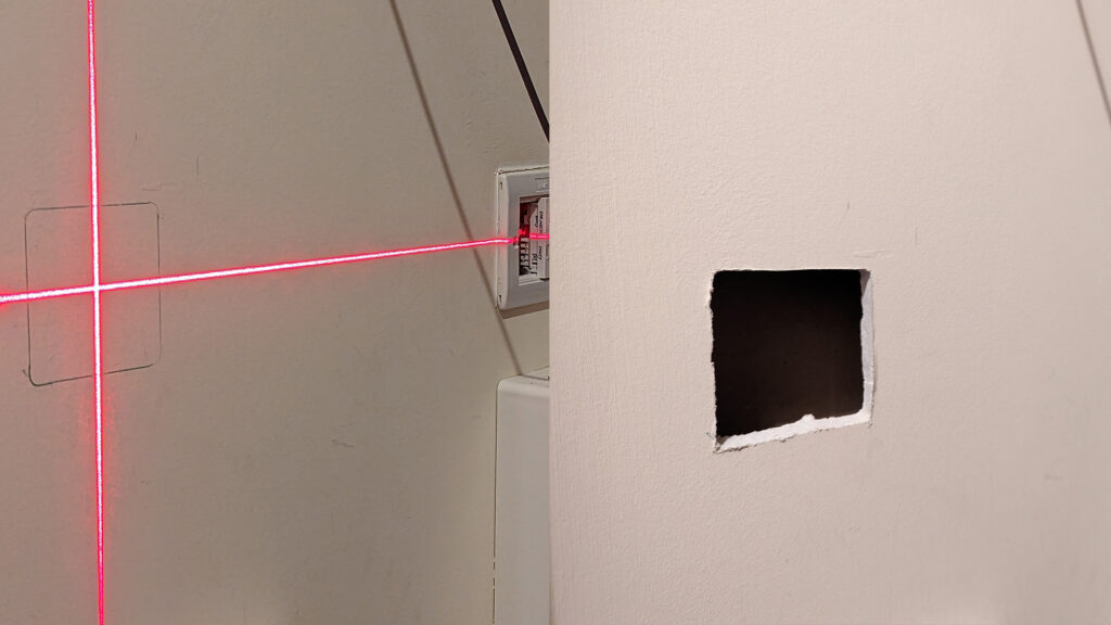
I made a small hole in the hidden plasterboard above hole #3, by poking my arm through hole #2 so that I could get the cable from the ceiling above the cupboard, down to where the RJ45 sockets will go.
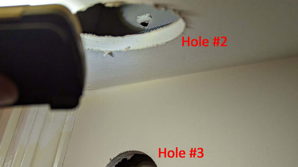
I removed the sharpened coat hanger from hole #1 in the hallway, going towards the cupboard, and widened the hole I’d made by poking my arm through hole #2, towards the hallway and twisting the pointed end of a Minotaur Double Sided Jab Saw & Scabbard 6″ from Toolstation into the hole made by the coat hanger.
I then bent the coat hanger around the hole in the end of my Super Rod Polypropylene Cable Tongue Draw Tape 3.6M from Screwfix.
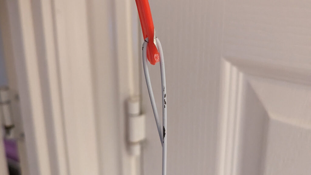
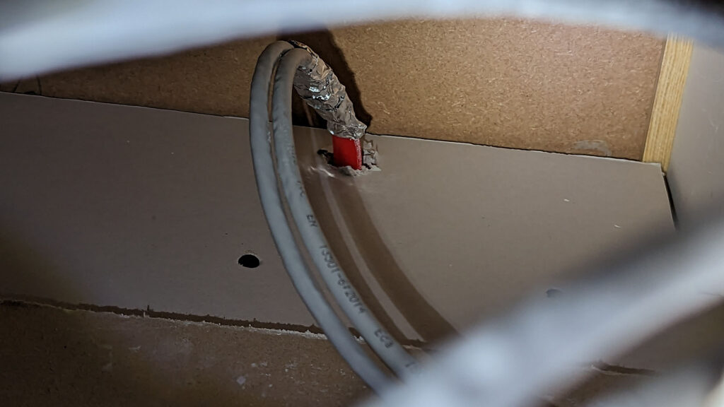
I put the coat hanger back through the hole I’d made between the hallway and above the cupboard ceiling, with the cable tongue still attached, using hole #1 as an access point.
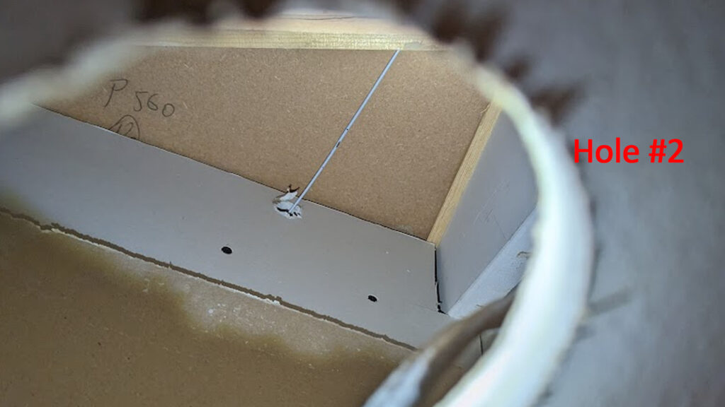
I grabbed the coat hanger with some pliars and pulled it down through hole #2, bringing the cable tongue through with it.
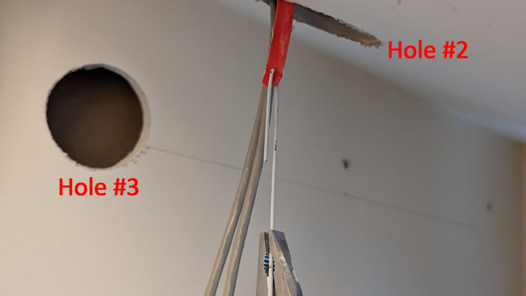
…leaving enough of the cable tongue hanging out of hole #1…
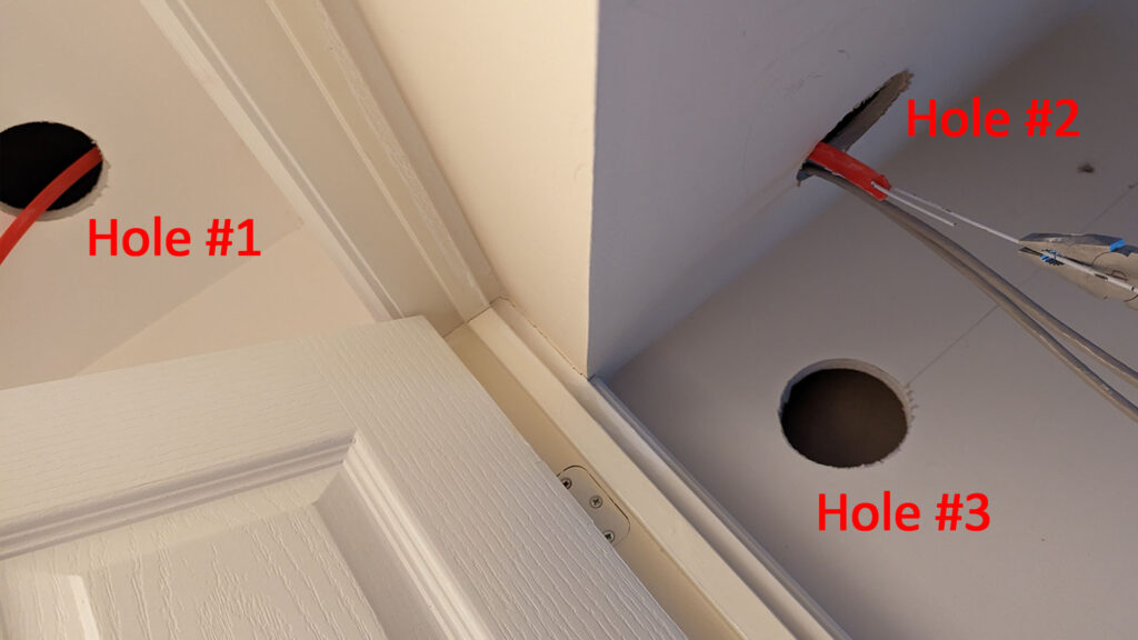
I removed the coat hanger from the cable tongue, poked my arm through hole #2 and fed the cable tongue down the hole I’d made above hole #3 and down the wall…
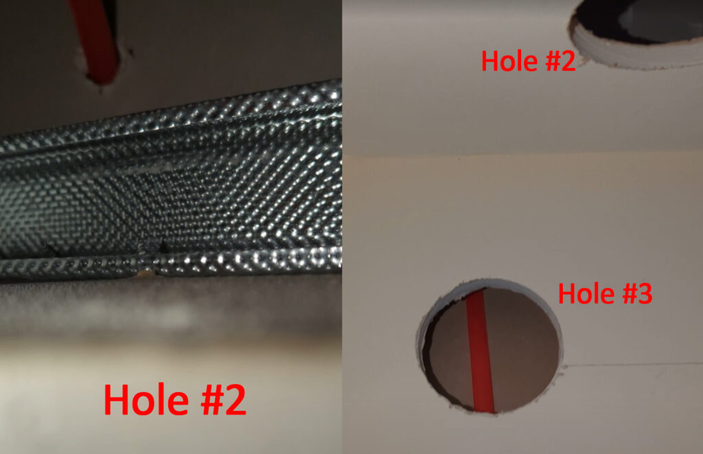
…and out of the hole I’d made for the RJ45 sockets. I used the only tape I had to hand, to fix the CAT6 to the cable tongue
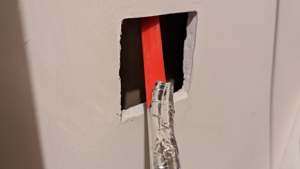
…and then pulled the cable tongue back up past hole #3, past hole #2, above the cupboard door, under the wood and out of hole #1.
Hole #4
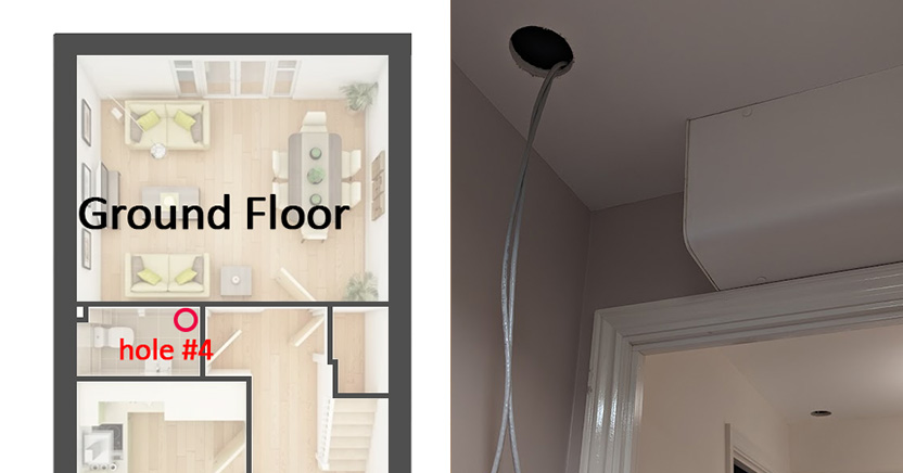
I then made hole #4 in the downstairs bathroom and fed the cable along from hole #1
Hole #5
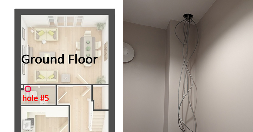
Hole #5 was made next to the vent stack in the downstairs bathroom, so I could find a route up to the first floor.
Hole #6
It was now time to try and get the cables up to the first floor through the vent stack. In the bathroom on the first floor, I drilled hole #6 in the corner, near to the floor.
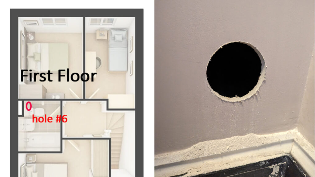
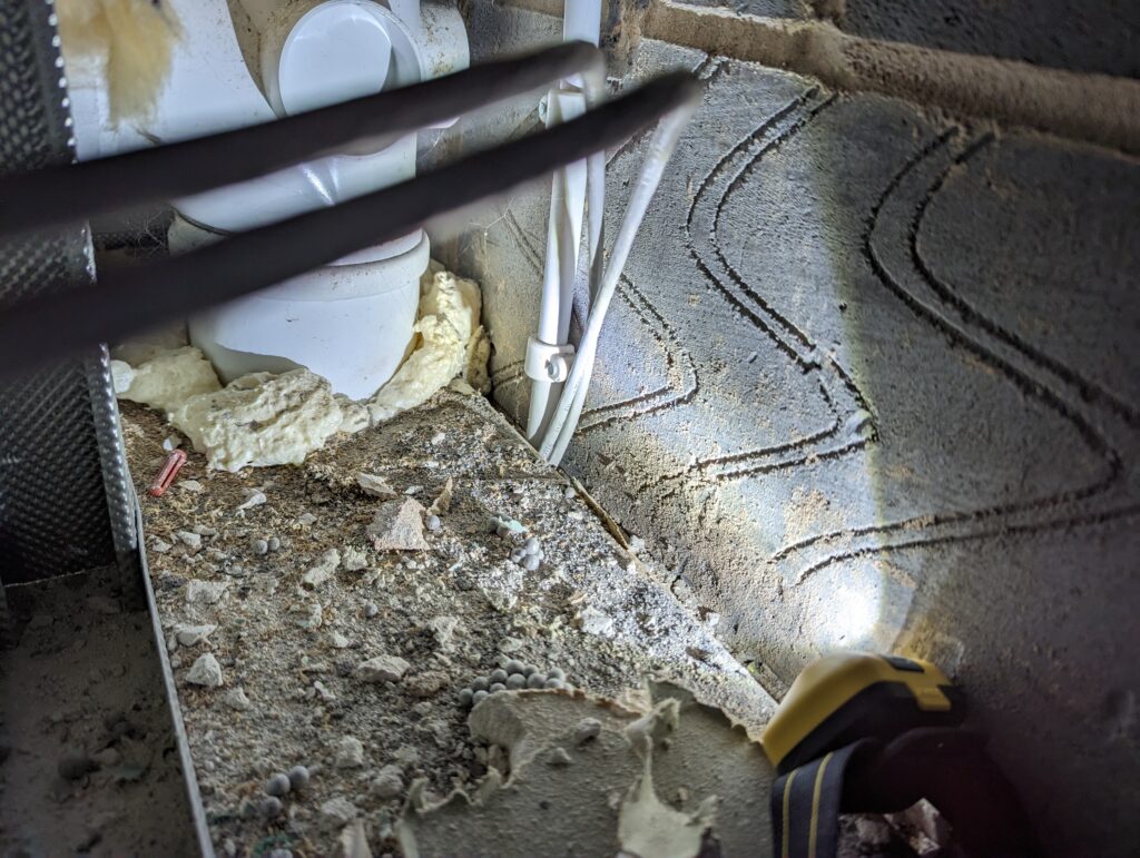
Looking through hole #6, between the wall and the floorboards, I could see a gap. Shining a light down there was visible from the downstairs bathroom…

I pushed the cable tongue from the upstairs bathroom, down along the side of the conduit circled above, and pulled it out of hole #5. As before, I taped the cables to the end of the cable tongue from hole #5, with a good overlap to provide more grip. I went back to hole #6 in the upstairs bathroom and pulled the cable tongue and cables up to the first floor.
Hole #7
This hole went directly above hole #6, near the ceiling so I could get access to the plasterboard above the vent stack boxing, into the loft.
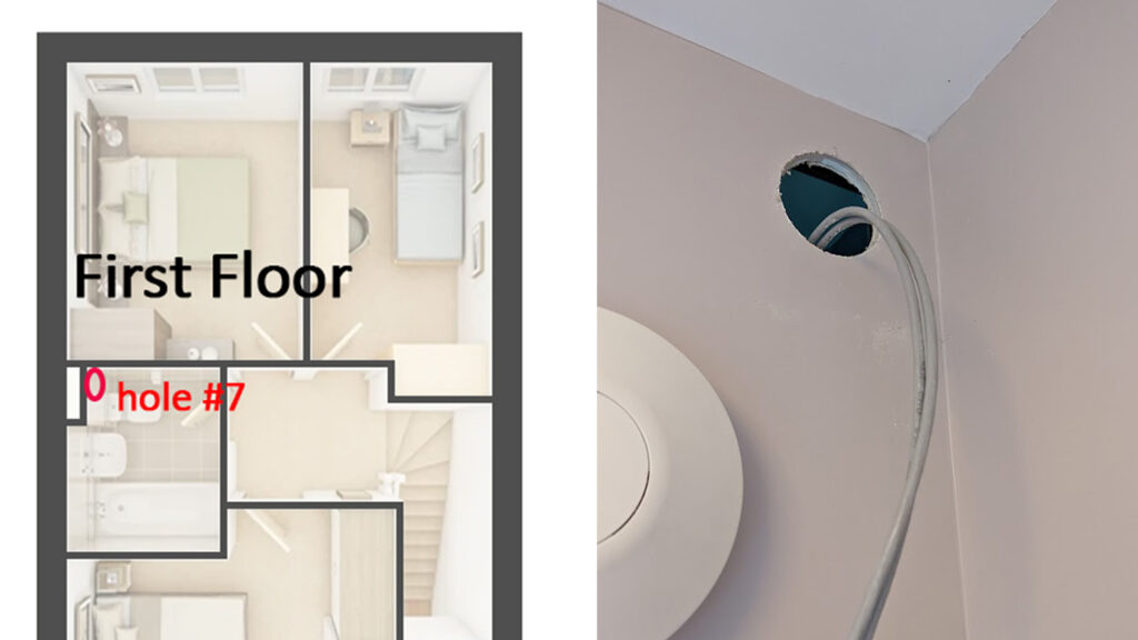
From hole #7, I made small hole in the plasterboard above to access the loft, checked the location in the loft and then widened the hole using the jab saw. I poked the cable tongue through, went up to the loft and pulled the cable tongue (and cables) through.
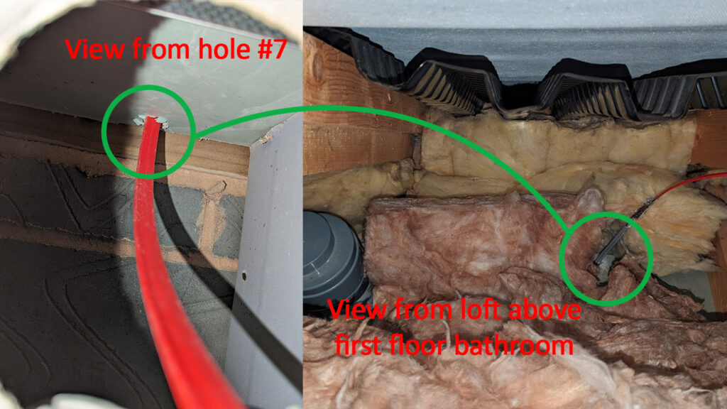
Running extra cables
With a lot of excess on the cables in the loft, I cut the other end (in the cupboard) giving myself plenty of slack to terminate into the wall sockets. At this point, I decided to run two more cables, giving me a total of four in the loft. This would allow me to run one to each room and one spare for a ceiling mounted WiFi access point.
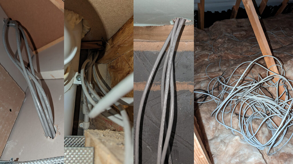
Down into the office
A bit about dot and dab
My house, being a new build has the plasterboard on external walls stuck to the block work using the dot and dab technique. Because the blobs of adhesive between the plasterboard and block work are quite thick, it leaves a void which is handy to route cables down.
Running the cable
I decided where to place my RJ45 wall socket in my office and, directly above this point, I cut a small hole in the plasterboard right below the ceiling. I then used my sharpened coat hanger to poke through the plasterboard. I went up to the loft to locate it and widened the hole by pushing a drill bit through.
Note: The square taken out of the plasterboard on the left was my first attempt, which failed, because my pilot hole showed me that there was a joist in the way.
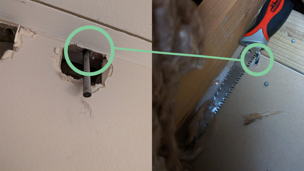
I widened the hole a little more, pulled one cable, from my bundle in the loft, over and pushed it down through the ceiling.
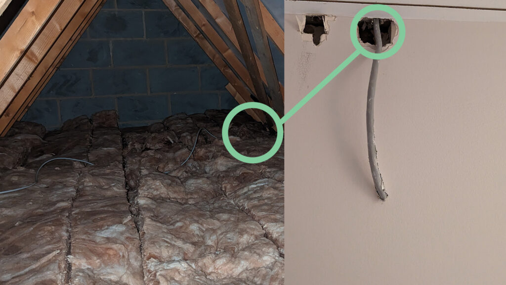
My dot and dab wall had a few blobs of adhesive directly below the hole I pulled the cable through, so I created a channel in the plasterboard using my stanley knife and chiselled the adhesive out of the way
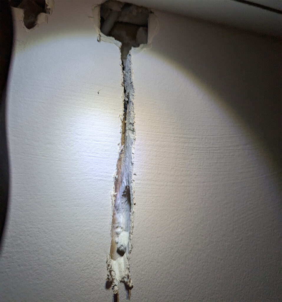
I made another hole further down the wall, towards where my socket will go. Pushed the cable tongue through the new hole and up to the channel. I attached the CAT6 to the cable tongue and pulled it back through.
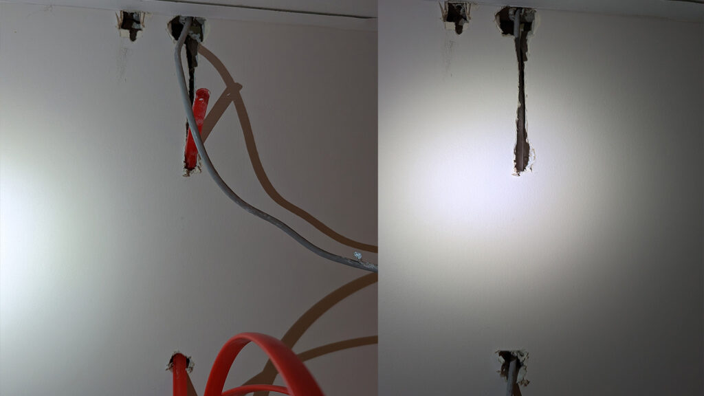
I cut a hole in the plasterboard to hold my RJ45 socket and repeated the above process until I reached the place where the socket will go.
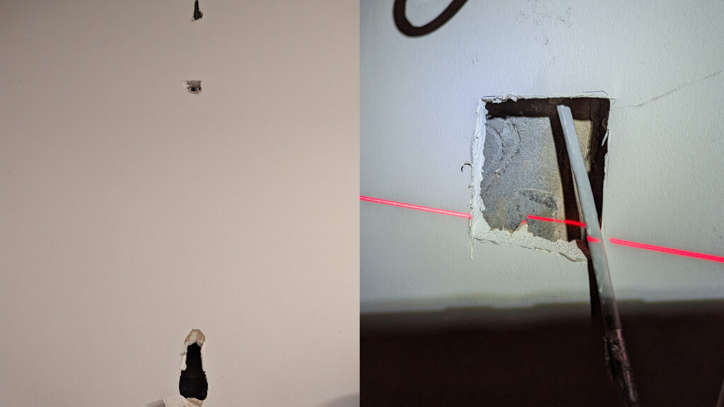
With hindsight, I could’ve skipped the holes between the channel at the top and the place where the socket went, but filler is cheap and plasterboard is easy to patch up!
Fitting the RJ45 sockets
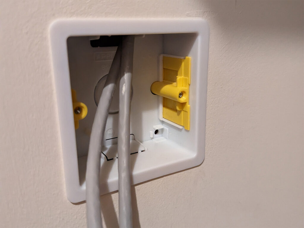
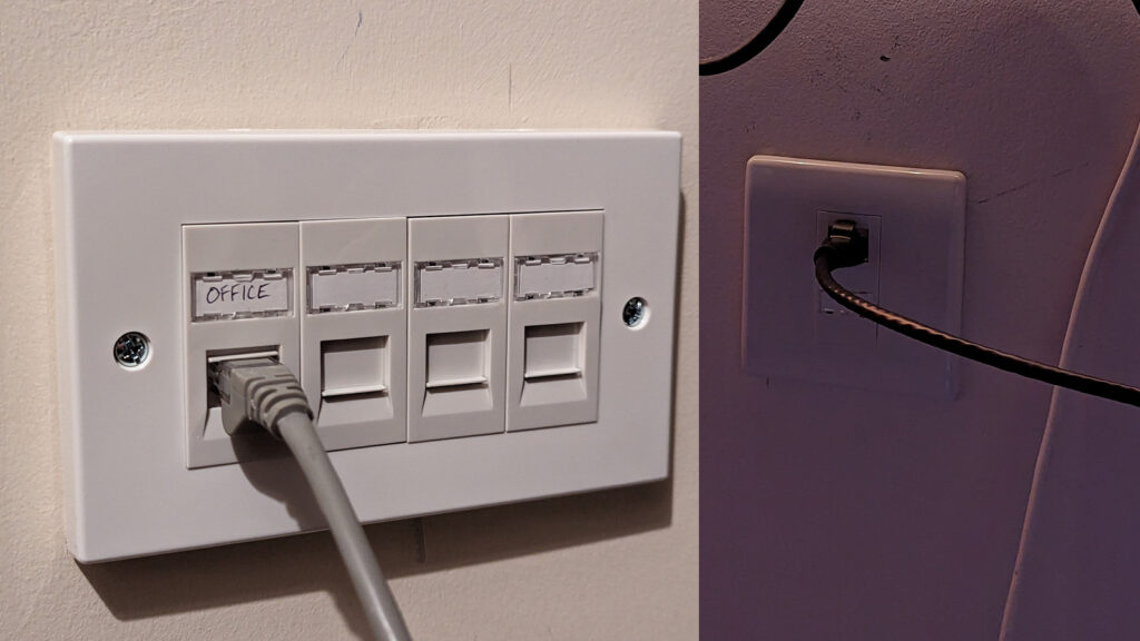
With the holes cut out in the office and cupboard, and the cables poking through, I fitted a 1-gang dry lining knockout box in the office and a 2-gang one in the cupboard.
Using my ‘Heavy Duty Punch Down Tool‘, I wired up the CAT6 cables to the keystones on the LAP Modular CAT 6 RJ45 Ethernet Sockets – 1 in the office, 4 in the cupboard.
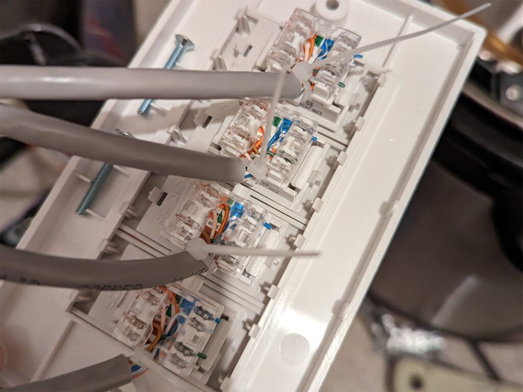
The modular RJ45 sockets were clipped into a LAP 4-Module Modular Faceplate in the cupboard and a LAP 1-Module Modular Faceplate White in the office and then screwed into the dry lining boxes.
Tidying up
Patching up the holes
I screwed a small piece of wood behind the hole, through the plasterboard
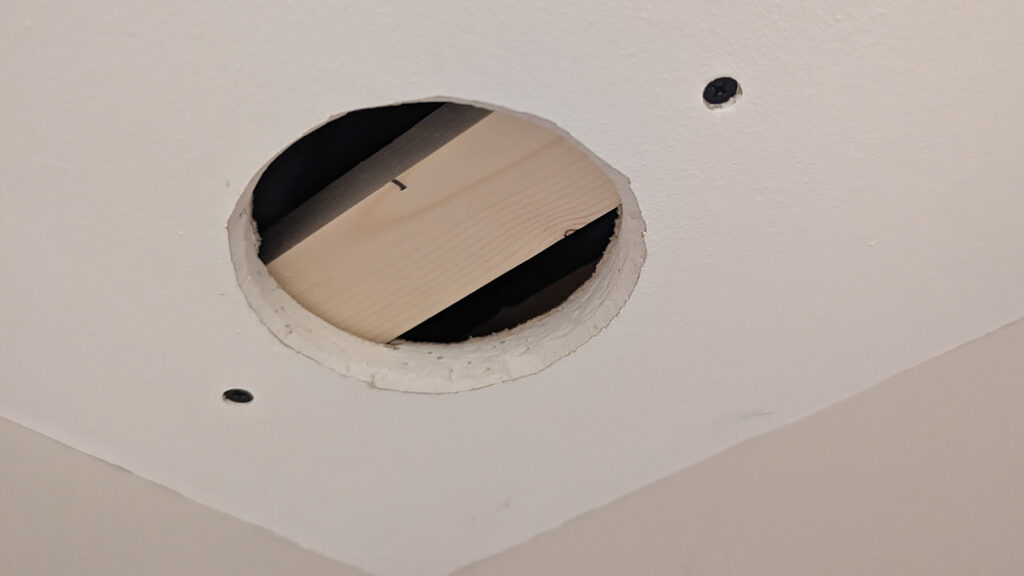
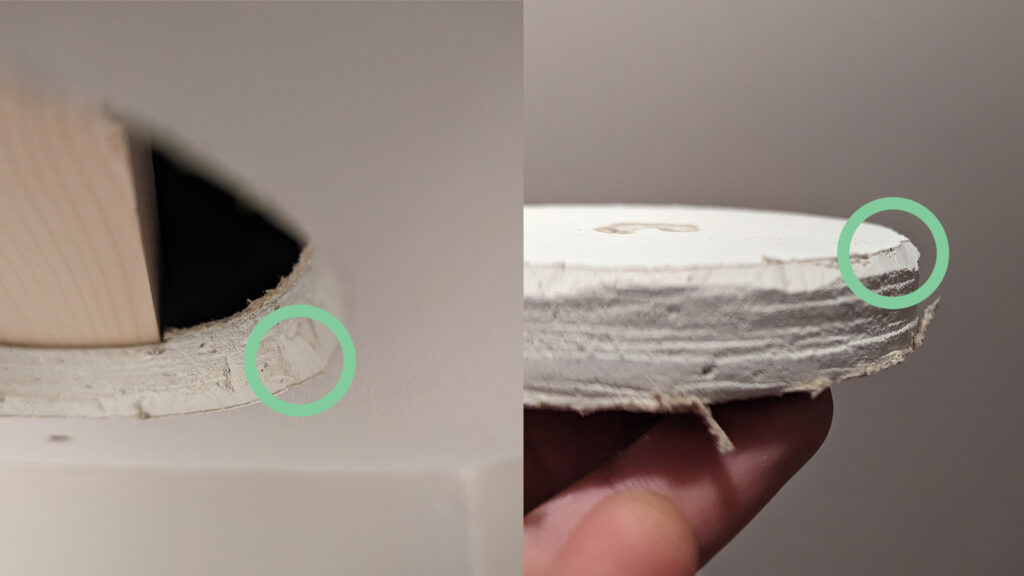
I cut around the hole, and the plasterboard disc, to create an angled edge to make it easier to fill the hole and remove any loose paper.
Using a piece of string, looped over the wood, I pulled down on the string gently as I drilled screws through the plasterboard disc
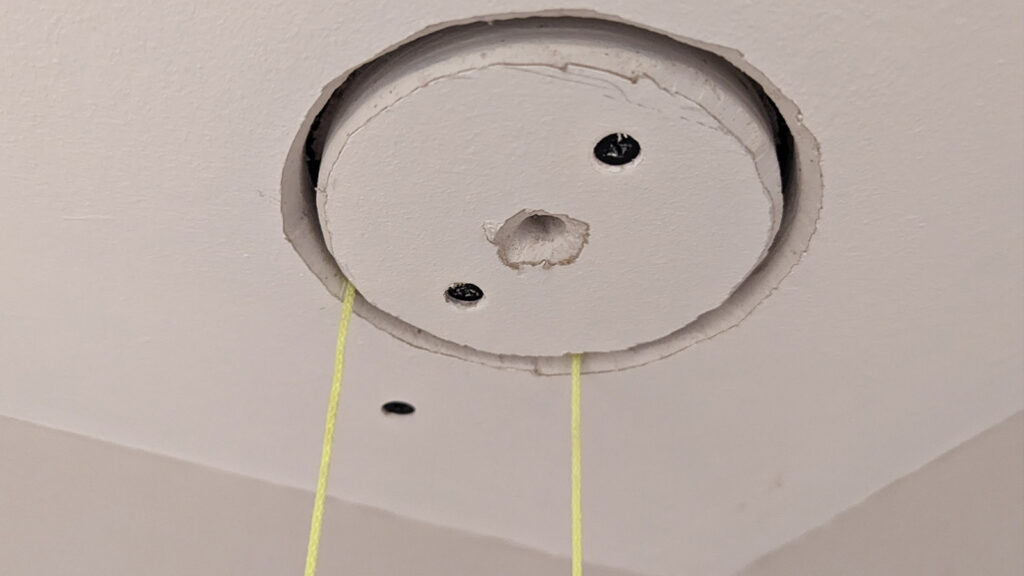
I dampened the exposed plaster (underneath the paper layer of the plasterboard) with a wet paint brush and applied filler
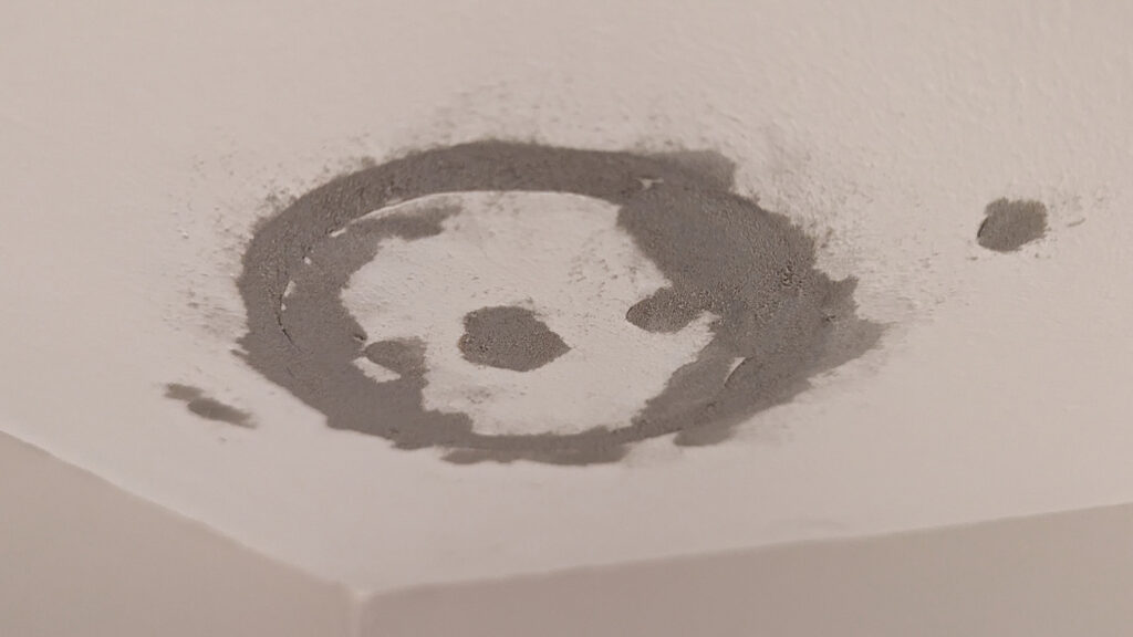
I repeated the process for all of the access holes I cut. I then sanded down the filler, reapplied filler to any low spots, and sanded again.

I kept applying thin layers of paint until the filler blended in.
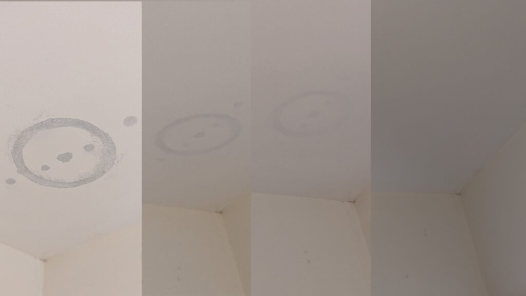
I applied thin layers of filler to the holes in the office, sanding high spots in between.
6 Comments
Chris · June 5, 2023 at 3:02 pm
Thank you! Just wanted to write this post as it’s exactly what I’m looking for down to the T! Only difference is our kitchen and living rooms are swapped.
We selected our TW house just after they closed options and wouldn’t let us add ethernet. Your guide will be my bible when I attempt this. I was planning on running an outdoor either from the cupboard near the door to the 3rd bedroom but my wife’s approval factor was low.
Seeing as the fuse board is also there this could be a great way of getting power to the loft also.
Luke · June 5, 2023 at 4:11 pm
You’re welcome! Super glad it makes someone else’s DIY job seem feasible (or increase the WAF).
Oh man, that’s so unfortunate. I also considered running the cable outside, but something about it didn’t sit right with me. I wanted it to be as hidden as possible, too.
Good luck for when you get started! When you give it a shot, please do report back if you find any helpful tips/tricks. I’m sure this won’t be the last time I retrofit network cables haha.
Ian W · April 11, 2024 at 5:57 am
No need to drill any holes in my Taylor Wimpey new build….I discovered that the internal telephone points were connected with Cat 6 cable. So when I was upgraded by BT Openreach to fibre, I changed all the internal phone sockets to RJ45 Taps. One hours work. Single Hall socket went to Bedroom 1 double RJ45 socket, bed 1 to living room double RJ45 socket, living room to bedroom 2 single RJ45 socket… Network works with two x 2.5gb switches and 2 x wifi 6e mesh units hard wired 2.5gb backhand. No drill holes in sight….
Luke · April 21, 2024 at 11:48 pm
Awesome! I’ve seen some people report CAT5e or CAT6 used for the phone sockets, but mine are all actual telephone-grade (CAT3, 2 twisted pairs). I did however find a CAT5e run from the cupboard under the stairs to the lounge, hidden behind blanking plates!
Tris · April 20, 2024 at 12:42 pm
I’ve got a Taylor Winpey home too, built CIRCA 2019 I think, in Winsford & wanetd to say thanks too. The idea of the vent/soil-stack which traverseses the ground, 1st & loft floors is a good idea albeit not ideal for me.
I simply wanted to get a CAT6/7 cable from the Study where the fibre router cabling & WiFi is (front of house) – to one bedrm where I’ve a PC (back of house). Subseuqently, I then wanted to get another to the living room where an LG G2 struggles to get reliable WiFI.
I assumed I could take the existing RF / TV antenna face-plate off & chase that RF wire to the loft fron the studt & then be able to drop down to the bedrm & do similar in the Lvg rm. After removing the RF faceplate, the RF cable that runs upward toward 1st floor / loft is encapsulated in plaster (?) just above the back-box tht the faceplate screw to – so I don’t know if thats just a dab – or its encapsulated in plaster all the way up.
In my case; the vent/soil-stack is at the back of the house and goes from kitchen (on ground) to bathrm on 1st & then up to loft. The downstairs loo has no vent/soil-stack – which alas is right next to the study too. The kitchen is at the back & study the front – so I’d have to run aacross the study wall trough to the loo (centre of house) – across the wall behind the loo into kitchen beneath the cupboards & chase the wall to the back and then it’d be at the vent/soil-stack.
Your solution, is brilliant & sheds light of the TW construction – though is more than I want to achieve. Meh! More thinking required! 🙂
Luke · April 21, 2024 at 11:50 pm
You’re not alone! I recently changed over a faceplate for my TV antenna and needed a bit more slack in the cable – I also found the top of the back box was completely blocked by plaster.